 I'm now looking into and planning my next motorcycle. Remember, I have quite a few production motorcycles but I really like working on them (mine - not yours) as much as riding them. Maybe that's why the bikes I've chosen to collect are tuning nightmares!
The built from scratch thing really does it for me. I've considered doing some alloy casting for the next project. I might go so far as to cast a block and other engine parts. If I can source a vintage engine, I would really like that as well.
If any followers know of any original older engines suitable for such a project - single or twin, I'd be interested in a lead.
I'm now looking into and planning my next motorcycle. Remember, I have quite a few production motorcycles but I really like working on them (mine - not yours) as much as riding them. Maybe that's why the bikes I've chosen to collect are tuning nightmares!
The built from scratch thing really does it for me. I've considered doing some alloy casting for the next project. I might go so far as to cast a block and other engine parts. If I can source a vintage engine, I would really like that as well.
If any followers know of any original older engines suitable for such a project - single or twin, I'd be interested in a lead.
10/18/09
I Think It's Done
I'm now looking into and planning my next motorcycle. Remember, I have quite a few production motorcycles but I really like working on them (mine - not yours) as much as riding them. Maybe that's why the bikes I've chosen to collect are tuning nightmares!
The built from scratch thing really does it for me. I've considered doing some alloy casting for the next project. I might go so far as to cast a block and other engine parts. If I can source a vintage engine, I would really like that as well.
If any followers know of any original older engines suitable for such a project - single or twin, I'd be interested in a lead.
10/17/09
 I machined this adapter/spacer for the sprocket. The webs in the hub best facilitated a three bolt pattern but I already had a four bolt pattern on the sprocket.
This spacer is first mounted to the hub with three bolts, then the sprocket is mounted to the spacer with four bolts.
This is a tricky deal because you can't just go drilling holes and plopping in any old bolt that fits. There are actually all sorts of rules for using fasteners. Look them up and use them. Learn about different fastener's strengths and weaknesses. More importantly, learn how they are designed to work. You can't just throw any bolt in a hole just because it is the right diameter.
In this case, it was a no-no to have threads inside the holes of two adjoining plates.
As shown in a prior post, the bolt pattern on the hub was set for me as a three bolt pattern. Through, measuring, aligning, and the use of transfer punches, I first made the four holes for the sprocket.
I machined this adapter/spacer for the sprocket. The webs in the hub best facilitated a three bolt pattern but I already had a four bolt pattern on the sprocket.
This spacer is first mounted to the hub with three bolts, then the sprocket is mounted to the spacer with four bolts.
This is a tricky deal because you can't just go drilling holes and plopping in any old bolt that fits. There are actually all sorts of rules for using fasteners. Look them up and use them. Learn about different fastener's strengths and weaknesses. More importantly, learn how they are designed to work. You can't just throw any bolt in a hole just because it is the right diameter.
In this case, it was a no-no to have threads inside the holes of two adjoining plates.
As shown in a prior post, the bolt pattern on the hub was set for me as a three bolt pattern. Through, measuring, aligning, and the use of transfer punches, I first made the four holes for the sprocket.
 I then radiused the center hole to fit the radius on the hub. I used some machinist radius gauges to check. I think it was 5/32" but I can't remember. I first used the lathe putting various radii on the hole, then sanded the remainder. According to the gauge, I hit it pretty close.
 Once mounted to the sprocket, I centered it on the hub (using the radiused center hole) and used a transfer punch to locate the holes, already in the hub, onto the spacer. I actually did two and located the third after the others were bolted down. I would rather have it slightly out of round than to have to wallow out one or two holes to align everything. This is why you can't just guess on these types of things. It introduces inaccuracies that build on themselves until you have a piece that is not precise at all.
Haven't ranted in a while. I spent nearly $20 just for the seven stainless fasteners for this part. Even then, I couldn't find what I needed and had to modify what I could find just to get it to "work". If I had $1 for every time I have had to shorten a bolt or modify a bolt head on this bike, I would have a few coffees to spare.
Well, I guess they don't carry shouldered machine-head bolts at Westlake/Ace. Because of this, I set the heads low and the 60 degree heads actually do most of the shear work rather than the threads. The proper use is to have no threads at all inside the hole. Note that I needed the machine heads as the plate had to be flush with the sprocket face. Here is one of the bolts turned down next to two originals for the comparison.
Once mounted to the sprocket, I centered it on the hub (using the radiused center hole) and used a transfer punch to locate the holes, already in the hub, onto the spacer. I actually did two and located the third after the others were bolted down. I would rather have it slightly out of round than to have to wallow out one or two holes to align everything. This is why you can't just guess on these types of things. It introduces inaccuracies that build on themselves until you have a piece that is not precise at all.
Haven't ranted in a while. I spent nearly $20 just for the seven stainless fasteners for this part. Even then, I couldn't find what I needed and had to modify what I could find just to get it to "work". If I had $1 for every time I have had to shorten a bolt or modify a bolt head on this bike, I would have a few coffees to spare.
Well, I guess they don't carry shouldered machine-head bolts at Westlake/Ace. Because of this, I set the heads low and the 60 degree heads actually do most of the shear work rather than the threads. The proper use is to have no threads at all inside the hole. Note that I needed the machine heads as the plate had to be flush with the sprocket face. Here is one of the bolts turned down next to two originals for the comparison.
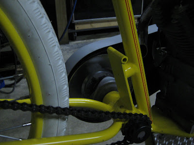
 I was more fortunate with the four bolts for the sprocket. I found them with shoulders but not in a machine head. I had a little more room on the back of the spacer and oriented then like the studs on a car spindle - sticking out from back to front. I had to taper one flat on each bolt head so it would clear a step on the hub OD.
Here is (a blurry shot of) the spacer first mounted to the hub. You can also see the four studs loosely fitted. If you look closely, you can see they are shouldered just enough to fit the sprocket - beautiful! That's the way bolts are supposed to work, using washers to give us the proper spacing, but how often do we do this? I am a little leary of the hub to spacer three-bolt interface but I am confident with this connection this.
I was more fortunate with the four bolts for the sprocket. I found them with shoulders but not in a machine head. I had a little more room on the back of the spacer and oriented then like the studs on a car spindle - sticking out from back to front. I had to taper one flat on each bolt head so it would clear a step on the hub OD.
Here is (a blurry shot of) the spacer first mounted to the hub. You can also see the four studs loosely fitted. If you look closely, you can see they are shouldered just enough to fit the sprocket - beautiful! That's the way bolts are supposed to work, using washers to give us the proper spacing, but how often do we do this? I am a little leary of the hub to spacer three-bolt interface but I am confident with this connection this.
 Then the sprocket mounted to the spacer. I used Locktight and torqued everything to about 25 ft/lbs. I want to distribute the stresses as evenly as possible.
 Well, that's about it. Not perfect, no cush drive, but back on two wheels.
10/9/09
Hub Issue
 The Worksman wheels are great - and the best option for such a project. The rims are actually pretty accurate to the time - rolled from 1/8" steel. The spokes are .120. The front hub is steel while the rear hub is alloy with a 4" drum brake and is threaded for a freewheel. It actually stopped the bike admirably. My first experience/test ride revealed that the brake was almost ineffective. Perhaps the shoes have partially bedded-in or perhaps my adjustments to the linkage improved the leverage but they (it) sure work better now. I did find myself dragging my feet a few times trying to attenuate my speed through the crowd at the show. The foot pedal is not in the most convenient place and people just weren't moving enough. Even so, at walking speed I could easily keep the bike upright with both feet up. Maybe all the road cycling I do helps with that but I was happy the frame performed with some stability.
Well, as mentioned, the alloy hub was designed for a freewheel. I covered earlier how I modified the supplied HD freewheel to hold a sprocket. I did not modify how it was mounted to the hub - via the traditional threads. These didn't last under the torque of the 13 HP engine. I did gag it a few times when the crowd would split and enjoyed the feeling of thrust. To me I thought that made the bike look like it really could do more than just putt through a fairground - like it really wanted to go...... and it did. The final moment was after leaving the show and riding around an adjacent block. About a block from the truck, and away from most of the crowd, I lost power. Looking down, I could see the PTO working. A guy walked up and told me the sprocket was "slipping". We ended up having a good conversation about the need for us to go to Davenport next year. He also noticed my, and I quote, "high dollar seat." He was correct on both accounts.
Well, my correction to the problem is not completely solved. I really would like a cush drive of sorts but I'm not sure how to do it with this hub. I think I will simply build a spacer that will mount solidly to the hub and then to the existing bolt pattern of the sprocket. With this setup, I realize that any future failure of the sprocket mount could be catastrophic. There will be no threads to give way, no free-spinning parts. The body of the hub would fail around the axle bearing, drop the wheel to the side, and send the sprocket into the spokes. Either of these last two events would lock up the rear in a quick way. In the nature of the original risk-takers, I will use this anyway, and hope that it helps me "keep my foot out of it." For those contemplating this type of project, cush drives are a huge deal and were designed and used from the beginning - as in the 1910s. It's not something to blow off saying, "Well it's not like I going to race it or anything." I hear these kinds of statements all the time and they are typically to justify either a lack of money, a lack of detail, or a lack of ingenuity. That said, I have isolated my rear sprocket/wheel from much of the vibration problem by using the belt driven sheave on the jackshaft. The primary reduction is elastic, so to speak. The secondary is chain driven and prone to more shock. The engine pulsations are what does a lot of the damage and can otherwise transmit themselves all the way to the contact patch between the ground and the tire. An all chain-driven application is at a higher risk of failure without some form of cush drive. This was one of the major advantages of the older leather belt-driven machines.
The Worksman wheels are great - and the best option for such a project. The rims are actually pretty accurate to the time - rolled from 1/8" steel. The spokes are .120. The front hub is steel while the rear hub is alloy with a 4" drum brake and is threaded for a freewheel. It actually stopped the bike admirably. My first experience/test ride revealed that the brake was almost ineffective. Perhaps the shoes have partially bedded-in or perhaps my adjustments to the linkage improved the leverage but they (it) sure work better now. I did find myself dragging my feet a few times trying to attenuate my speed through the crowd at the show. The foot pedal is not in the most convenient place and people just weren't moving enough. Even so, at walking speed I could easily keep the bike upright with both feet up. Maybe all the road cycling I do helps with that but I was happy the frame performed with some stability.
Well, as mentioned, the alloy hub was designed for a freewheel. I covered earlier how I modified the supplied HD freewheel to hold a sprocket. I did not modify how it was mounted to the hub - via the traditional threads. These didn't last under the torque of the 13 HP engine. I did gag it a few times when the crowd would split and enjoyed the feeling of thrust. To me I thought that made the bike look like it really could do more than just putt through a fairground - like it really wanted to go...... and it did. The final moment was after leaving the show and riding around an adjacent block. About a block from the truck, and away from most of the crowd, I lost power. Looking down, I could see the PTO working. A guy walked up and told me the sprocket was "slipping". We ended up having a good conversation about the need for us to go to Davenport next year. He also noticed my, and I quote, "high dollar seat." He was correct on both accounts.
Well, my correction to the problem is not completely solved. I really would like a cush drive of sorts but I'm not sure how to do it with this hub. I think I will simply build a spacer that will mount solidly to the hub and then to the existing bolt pattern of the sprocket. With this setup, I realize that any future failure of the sprocket mount could be catastrophic. There will be no threads to give way, no free-spinning parts. The body of the hub would fail around the axle bearing, drop the wheel to the side, and send the sprocket into the spokes. Either of these last two events would lock up the rear in a quick way. In the nature of the original risk-takers, I will use this anyway, and hope that it helps me "keep my foot out of it." For those contemplating this type of project, cush drives are a huge deal and were designed and used from the beginning - as in the 1910s. It's not something to blow off saying, "Well it's not like I going to race it or anything." I hear these kinds of statements all the time and they are typically to justify either a lack of money, a lack of detail, or a lack of ingenuity. That said, I have isolated my rear sprocket/wheel from much of the vibration problem by using the belt driven sheave on the jackshaft. The primary reduction is elastic, so to speak. The secondary is chain driven and prone to more shock. The engine pulsations are what does a lot of the damage and can otherwise transmit themselves all the way to the contact patch between the ground and the tire. An all chain-driven application is at a higher risk of failure without some form of cush drive. This was one of the major advantages of the older leather belt-driven machines.
 This pic shows the webs cast in the hub. I must avoid those when laying out a bolt pattern. A friend managed to get six bolts, two between each web, into his identical hub. I am going with three.
 First I used a 5/8" end mill to take down some of the casting so that the bolt heads would be on a flat surface. My friend bolted from the outside, threaded his hub, and added nuts inside. I feel a solid bolt shoulder would be best in my case - no more stress risers than absolutely necessary.
 I then drilled a 1/8" hole and flipped the wheel.
 Using a degree chuck(super spacer, whatever), I spaced two more identical holes (120 degrees apart) for a three bolt pattern perfectly spaced. One could also mount the hub on it's axle and affix a degree wheel(made from a printout available on the web) onto the hub and, using a fixed pointer, rotate the wheel the required amount and mark/drill or mark directly at 120 degree points at equal distances from the axle. How far out? Well, that's why I first flipped the wheel to identify the hub ribs and drilled the first hole from that side. One could even mount the wheel on the bike and scribe a line around the hub for the nominal bolt pattern line. Intersect the line with the degree wheel marks and there is your bolt pattern. You don't have to have many machine tools to do a job right. What you need is the patience to do it right. The layout is all the same, the tools just make the holes. If you do such things, take the extra time to center punch any marks for drilling, start with a small bit, and really clamp down the work - not just for safety but for much increased accuracy and neatness. A hole is not just a hole!
Well, that's all for now. I have to build the spacer and mate that to the sprocket - maybe next week.
Using a degree chuck(super spacer, whatever), I spaced two more identical holes (120 degrees apart) for a three bolt pattern perfectly spaced. One could also mount the hub on it's axle and affix a degree wheel(made from a printout available on the web) onto the hub and, using a fixed pointer, rotate the wheel the required amount and mark/drill or mark directly at 120 degree points at equal distances from the axle. How far out? Well, that's why I first flipped the wheel to identify the hub ribs and drilled the first hole from that side. One could even mount the wheel on the bike and scribe a line around the hub for the nominal bolt pattern line. Intersect the line with the degree wheel marks and there is your bolt pattern. You don't have to have many machine tools to do a job right. What you need is the patience to do it right. The layout is all the same, the tools just make the holes. If you do such things, take the extra time to center punch any marks for drilling, start with a small bit, and really clamp down the work - not just for safety but for much increased accuracy and neatness. A hole is not just a hole!
Well, that's all for now. I have to build the spacer and mate that to the sprocket - maybe next week.
10/4/09
The unveiling
 Took it to Ralph Wayne's Backyard Nationals yesterday. Unloaded it down the street and rode it up. A gate guy was waiving bikes onto a side street but waived me through. Huge attention getter as I rode through a sea of people on the blocked-off roads with people reaching for their cameras. I couldn't help but think they would be disappointed to see up close that it was a fake. Everyone assured me it was still cool and plenty stopped to look and ask questions. "Where did you get this part?", "What frame did you use?", What year is that engine?" Quite a few thought it was a Harley engine - shows how many posers are there. I became more and more confident raising eyebrows by saying it's a Briggs & Stratton. The biggest boost was saying I fabricated it, frame and all, myself. In the past, I've taken a nice cafe racer, a vintage BMW, a production 2-stroke road racer(loudest!), and this. This got by far the most attention - what I've found I crave for my troubles.
 Soon, one of the show guys told me to take it up under the main tent(said he was cherry picking a few bikes). I felt a little sheepish but finally rode it up there.
Look at all the Harley-types around it!
Soon, one of the show guys told me to take it up under the main tent(said he was cherry picking a few bikes). I felt a little sheepish but finally rode it up there.
Look at all the Harley-types around it!

 At the end, I fired it up a rode to the truck. Took it for a side journey around the block and spun the threads on the rear hub! An aluminum alloy hub with
this torque is just too much. I'll likely mount a sprocket carrier directly to the hub face and take it easy next time. The acceleration is fun though.
At the end, I fired it up a rode to the truck. Took it for a side journey around the block and spun the threads on the rear hub! An aluminum alloy hub with
this torque is just too much. I'll likely mount a sprocket carrier directly to the hub face and take it easy next time. The acceleration is fun though.
10/2/09
 I get a lot of inquiries about this project. I have received e-mails from Belgium, Japan, Australia, and all over the U.S. Well, out of the blue I get one from another Dave who sent scans of the head tube decal and primary cover decals. He felt they were a set of original decals. If not, they were still a Godsend. What luck! I have not been able to make heads nor tails of the head tube decal until now. It did reveal to me that my interpretation of the gray drop shadow on the tank decal was incorrect - it is actually a teal green. I have always thought this was an illusion or lighting effect until I looked again after receiving David's scans. I'll either redo them, hand paint over them, or blow it off. That head tube decal was greatly appreciated. In it's full size it is too big as my head tube is not as large as the original. I put it on anyway and I like the way it finishes up the front end.
So much more is known and shared about this marque now than when I started. Makes me want to start over again!
I did sort the brake out a bit and it is much better. Add to this that I had yet to finish weld the brake pedal pivot tube for that inaugural ride. It didn't contribute to the poor braking but I am fortunate it didn't completely fail. It did so once back in the garage as I checked for flex in the linkage - close one and lesson learned.
I get a lot of inquiries about this project. I have received e-mails from Belgium, Japan, Australia, and all over the U.S. Well, out of the blue I get one from another Dave who sent scans of the head tube decal and primary cover decals. He felt they were a set of original decals. If not, they were still a Godsend. What luck! I have not been able to make heads nor tails of the head tube decal until now. It did reveal to me that my interpretation of the gray drop shadow on the tank decal was incorrect - it is actually a teal green. I have always thought this was an illusion or lighting effect until I looked again after receiving David's scans. I'll either redo them, hand paint over them, or blow it off. That head tube decal was greatly appreciated. In it's full size it is too big as my head tube is not as large as the original. I put it on anyway and I like the way it finishes up the front end.
So much more is known and shared about this marque now than when I started. Makes me want to start over again!
I did sort the brake out a bit and it is much better. Add to this that I had yet to finish weld the brake pedal pivot tube for that inaugural ride. It didn't contribute to the poor braking but I am fortunate it didn't completely fail. It did so once back in the garage as I checked for flex in the linkage - close one and lesson learned.
 This is pretty much how it now looks - sans the small side decals which I opted to place on the battery/tool box. That thing is so stuffed, even with just a 3.3amp AGM battery, that is is a pain to work in there. The key is on the left.
I widened the rear stand and added spacers to the pivots so the stand would better clear the axle nuts. The fender is visible too. Since this photo I have distressed it a bit and rubbed down the shabby pin striping to a "worn condition".
I bought some of Felt's new Quick Trick cruiser tires in all black and they are the closest to the old combination tread I have found. There has always been a void in this area IMO. They come is several colors including cream/white so, should I stay with white, I will go with those.
I now have 4 rides up and down the street on the bike and my confidence foolishly grows.
Tomorrow I will take it to Ralph Wayne's Backyard Nationals to see what kind of response I get.
This is pretty much how it now looks - sans the small side decals which I opted to place on the battery/tool box. That thing is so stuffed, even with just a 3.3amp AGM battery, that is is a pain to work in there. The key is on the left.
I widened the rear stand and added spacers to the pivots so the stand would better clear the axle nuts. The fender is visible too. Since this photo I have distressed it a bit and rubbed down the shabby pin striping to a "worn condition".
I bought some of Felt's new Quick Trick cruiser tires in all black and they are the closest to the old combination tread I have found. There has always been a void in this area IMO. They come is several colors including cream/white so, should I stay with white, I will go with those.
I now have 4 rides up and down the street on the bike and my confidence foolishly grows.
Tomorrow I will take it to Ralph Wayne's Backyard Nationals to see what kind of response I get.
9/20/09
Tidying Up
 Here's the kill switch I fabricated. This grounds out the coils. It functions like and looks very similar to an original except the spring is bent to conform to the shape of the bars. Before I trimmed the metal spring around the button, I got a nasty shock when the web of my hand hit it. Works perfectly now.

 Here's the battery box I'm building. It fits snugly in front of the rear wheel. I hope to relocate the ignition switch and maybe the regulator add a small AGM battery so I can start it without a jump. I left enough room for a fender. You can see I cut out an access door on the right side. I hope to find a piano hinge to tack in place for the door.
 To mount it I fabricated two brackets similar to those that hold the fuel tank. I made two backing strips and drilled/threaded two holes in each for the straps. These go inside the box and are plug welded to the front. 1/4" X 20 bolts hold it on.
 Here it is loosely in place. Since I made a mock up out of cardboard, it actually fits quite snugly. Here it is hanging as I tried to slide a fender in there. The fender will be bobbed and will have a kick stand clip on it. It will mount under the box and with brackets in the back.
Here's how the right side looks without the door:
Here it is loosely in place. Since I made a mock up out of cardboard, it actually fits quite snugly. Here it is hanging as I tried to slide a fender in there. The fender will be bobbed and will have a kick stand clip on it. It will mount under the box and with brackets in the back.
Here's how the right side looks without the door:
 Below is one of the axle adjusters. Having the adjusting bolts hitting just the washers worked until they were tight - then they would slip over the front edge of the washers and do nothing. It was just something I had put off.
I notched the washers and then center-drilled some bar stock in the lathe. The tubes are only about .300 long. I laid the tubes in the notches of the washers and brazed them in place. Do this on some scrap aluminum so it won't stick. I didn't jig these. The pieces were small and wanting to shift around a bit but once the flux melted it was as if that held things in place. You can tap things in position with the cool brazing rod while you heat the parts. Once done, the back surface sits flush with the dropout and aligns perfectly with the bolt. I left the parts rough and didn't clean up all the excess brazing - it fits the look of the bike.
Below is one of the axle adjusters. Having the adjusting bolts hitting just the washers worked until they were tight - then they would slip over the front edge of the washers and do nothing. It was just something I had put off.
I notched the washers and then center-drilled some bar stock in the lathe. The tubes are only about .300 long. I laid the tubes in the notches of the washers and brazed them in place. Do this on some scrap aluminum so it won't stick. I didn't jig these. The pieces were small and wanting to shift around a bit but once the flux melted it was as if that held things in place. You can tap things in position with the cool brazing rod while you heat the parts. Once done, the back surface sits flush with the dropout and aligns perfectly with the bolt. I left the parts rough and didn't clean up all the excess brazing - it fits the look of the bike.

6/13/09
5/31/09
Seat Update
 Got the seat this week. Took about a month longer than predicted but it is nice and really helps the look. The mock seat I made was almost identical in shape and width and only about 1/2" too long in front. Amazing how close you can get if you cross examine enough pics of parts on the web.
I couldn't really sit on this thing up until now without the proper seat but now I have few excuses - I'm anxious to ride this thing.
I brazed some tubing onto flat bar for the seat post then made some brackets to support the rear of the seat from the seat stays. This was a common way to mount them.
Got the seat this week. Took about a month longer than predicted but it is nice and really helps the look. The mock seat I made was almost identical in shape and width and only about 1/2" too long in front. Amazing how close you can get if you cross examine enough pics of parts on the web.
I couldn't really sit on this thing up until now without the proper seat but now I have few excuses - I'm anxious to ride this thing.
I brazed some tubing onto flat bar for the seat post then made some brackets to support the rear of the seat from the seat stays. This was a common way to mount them.
 I needed to braze some tabs on the seat stays so I "jigged" them up to keep them level.
 I used 3/4" flat stock with a few funky bends for the seat supports. Here's how they turned out.

 Of course I sat on it and it is loooooong. I needed a quick model so Linda stepped in for the deed. After a few choice comments about not trusting my welds, she committed enough to sit on it.

4/19/09
Pedal Solution
 These are shots of the pedals and crank "carrier" installed. The bottom bracket was already occupied by the counter shaft so I had to come up with another way to mount the pedals in a way that was more pleasing than just screwing them to the frame, etc. Though not functional, there were many motorcycles of the era that had cranks and pedals that were fixed in place. By the late teens, motors had enough torque that pedal assistance was no longer required on hills. Search for images and you will see examples. Some merely fixed the crank to the chainstays with a bracket. I think there was a problem breaking a 20-year tradition by eliminating pedals, and the crank, as the traditional form of foot rest.
These Torrington pedals were nice and worn.
These are shots of the pedals and crank "carrier" installed. The bottom bracket was already occupied by the counter shaft so I had to come up with another way to mount the pedals in a way that was more pleasing than just screwing them to the frame, etc. Though not functional, there were many motorcycles of the era that had cranks and pedals that were fixed in place. By the late teens, motors had enough torque that pedal assistance was no longer required on hills. Search for images and you will see examples. Some merely fixed the crank to the chainstays with a bracket. I think there was a problem breaking a 20-year tradition by eliminating pedals, and the crank, as the traditional form of foot rest.
These Torrington pedals were nice and worn.
 I substituted the rubber blocks with some large diamond pattern blocks that look more the part. Here's a before and after shot. I like the larger and more open look achieved.
 Quite a bit more narrow than with the footboards, huh?

4/4/09
Does it run?
 Linda took this pic after I rolled it outside to let it breathe a bit.
Earlier I applied the decal on the right side. Registration to the white mask was close but I did have to make a few small cuts. No biggie.
Linda took this pic after I rolled it outside to let it breathe a bit.
Earlier I applied the decal on the right side. Registration to the white mask was close but I did have to make a few small cuts. No biggie.


 I wrapped the grips with herringbone twill tape I got from my late grandmother a few years back. It is dyed black with leather dye and dried overnight. I hope the grips take on a grimy, sticky look.
 Well, does it run?
4/3/09
Decal Love
Okay so I worked on the primary guard, found some old rubber pedal block inserts to make correct looking pedals, and bought another two-stroke road bike. I guess it's time to get over this decal hump before the flame dies down and I lose interest. Worse comes to worse, I sand these decals off and buy white decal paper and go that route. Remember the decals I printed were on clear paper so they were somewhat translucent and the areas that needed to be white were not.
I decided to make a mask and put down a thin layer of white paint behind the decal to help the colors stay true and to reveal the white lettering and drop shadows. White is a color that doesn't print on decal paper(unless you use an obsolete Alps printer). Thus the need for a mask. Registration could be tricky as I would need to keep this white mask slightly smaller than the decal except where the white meets the edges. I don't want a white border where one shouldn't be. What a pain!....... but with the obstacles I've already faced, I'm properly motivated to do this. After carefully cutting a negative mask from one of the paper prints of the decal, I sprayed adhesive on the back and somewhat arbitrarily placed it on the tank. I had to add in a few areas in the center of letters to allow the yellow to show through the in the end. I broke out the old Vega 2000 airbrush from the modeling days and mixed some gloss white pretty thin. A spray can would have been faster but would have crept behind the mask easier if and when it lifted at the edges and would have been thicker - leaving a harder edge. Also, I enjoyed digging out my airbrush and compressor. 175psi would be a little overkill on this part. After painting, I removed the mask and rubbed off some of the adhesive from around the white. When the paint had dried, I wet sanded it lightly with 400 and soapy water to knock off any edges. Off to the basement to see if I had any setting solution. Found two bottles that were about 13 years old. A third was the really good stuff but it was dried up. FYI, setting solutions take decals to a different level. The dried up stuff, for example, literally melts and swells the decal after application and, if you don't freak out and wipe it off, it shrinks it back down conforming it to about any contour you give it. It's crazy stuff. These two are much milder but they are all I have.

 I cut the decal oversized as the slight excess would be clear. After soaking the decal in warm water with a drop or two of Dawn soap, I slid it into place and tried to register it with the mask. Don't forget to use a microwave safe bacon pan for soaking and spill the water wherever possible. I rolled excess water out from under the decal with an old tee shirt. Then came the Solva Set around the edges with a small brush encouraging it into any bubbles at the edges. I'll let it dry overnight then check for silvering or bubbles. A pin prick or Exacto slice and more solution usually solves that.
The other side of the tank may be a little off as I reused the masking template and a "peninsula" of letters can be off by a one or two mm. I reinstalled the positive part of the mask to help. If this happened(I have yet to apply the decal to the other side), I'll slice the letters of the decal apart where needed and shift them to fit. No biggie and as Dad used to say, "You'll never see it on a galloping horse."
Below is a shot of the side I applied. Registration isn't perfect but better than I expected. Just wait 'till they both fade to white after about a month! I don't hope to deceive anyone into thinking it's anything but a decal..... or that this is actually a Cyclone!
I cut the decal oversized as the slight excess would be clear. After soaking the decal in warm water with a drop or two of Dawn soap, I slid it into place and tried to register it with the mask. Don't forget to use a microwave safe bacon pan for soaking and spill the water wherever possible. I rolled excess water out from under the decal with an old tee shirt. Then came the Solva Set around the edges with a small brush encouraging it into any bubbles at the edges. I'll let it dry overnight then check for silvering or bubbles. A pin prick or Exacto slice and more solution usually solves that.
The other side of the tank may be a little off as I reused the masking template and a "peninsula" of letters can be off by a one or two mm. I reinstalled the positive part of the mask to help. If this happened(I have yet to apply the decal to the other side), I'll slice the letters of the decal apart where needed and shift them to fit. No biggie and as Dad used to say, "You'll never see it on a galloping horse."
Below is a shot of the side I applied. Registration isn't perfect but better than I expected. Just wait 'till they both fade to white after about a month! I don't hope to deceive anyone into thinking it's anything but a decal..... or that this is actually a Cyclone!

 After carefully cutting a negative mask from one of the paper prints of the decal, I sprayed adhesive on the back and somewhat arbitrarily placed it on the tank. I had to add in a few areas in the center of letters to allow the yellow to show through the in the end. I broke out the old Vega 2000 airbrush from the modeling days and mixed some gloss white pretty thin. A spray can would have been faster but would have crept behind the mask easier if and when it lifted at the edges and would have been thicker - leaving a harder edge. Also, I enjoyed digging out my airbrush and compressor. 175psi would be a little overkill on this part. After painting, I removed the mask and rubbed off some of the adhesive from around the white. When the paint had dried, I wet sanded it lightly with 400 and soapy water to knock off any edges. Off to the basement to see if I had any setting solution. Found two bottles that were about 13 years old. A third was the really good stuff but it was dried up. FYI, setting solutions take decals to a different level. The dried up stuff, for example, literally melts and swells the decal after application and, if you don't freak out and wipe it off, it shrinks it back down conforming it to about any contour you give it. It's crazy stuff. These two are much milder but they are all I have.

 I cut the decal oversized as the slight excess would be clear. After soaking the decal in warm water with a drop or two of Dawn soap, I slid it into place and tried to register it with the mask. Don't forget to use a microwave safe bacon pan for soaking and spill the water wherever possible. I rolled excess water out from under the decal with an old tee shirt. Then came the Solva Set around the edges with a small brush encouraging it into any bubbles at the edges. I'll let it dry overnight then check for silvering or bubbles. A pin prick or Exacto slice and more solution usually solves that.
The other side of the tank may be a little off as I reused the masking template and a "peninsula" of letters can be off by a one or two mm. I reinstalled the positive part of the mask to help. If this happened(I have yet to apply the decal to the other side), I'll slice the letters of the decal apart where needed and shift them to fit. No biggie and as Dad used to say, "You'll never see it on a galloping horse."
Below is a shot of the side I applied. Registration isn't perfect but better than I expected. Just wait 'till they both fade to white after about a month! I don't hope to deceive anyone into thinking it's anything but a decal..... or that this is actually a Cyclone!
I cut the decal oversized as the slight excess would be clear. After soaking the decal in warm water with a drop or two of Dawn soap, I slid it into place and tried to register it with the mask. Don't forget to use a microwave safe bacon pan for soaking and spill the water wherever possible. I rolled excess water out from under the decal with an old tee shirt. Then came the Solva Set around the edges with a small brush encouraging it into any bubbles at the edges. I'll let it dry overnight then check for silvering or bubbles. A pin prick or Exacto slice and more solution usually solves that.
The other side of the tank may be a little off as I reused the masking template and a "peninsula" of letters can be off by a one or two mm. I reinstalled the positive part of the mask to help. If this happened(I have yet to apply the decal to the other side), I'll slice the letters of the decal apart where needed and shift them to fit. No biggie and as Dad used to say, "You'll never see it on a galloping horse."
Below is a shot of the side I applied. Registration isn't perfect but better than I expected. Just wait 'till they both fade to white after about a month! I don't hope to deceive anyone into thinking it's anything but a decal..... or that this is actually a Cyclone!

3/28/09
Tidying up
There have been a few things that I just couldn't put off much longer and I thought I'd get off the decal thing for a while.
Here's a shot of the old exhaust and long dipstick tube:
 The original exhaust from the front cylinder passed back along the top of the motor where the back cylinder tee'd in. Together they dropped down the back. I knew I wanted them to drop down individually but didn't want soot directly on my foot or on the clutch or countershaft. Here's what I came up with.
 The front pipe:
 The rear pipe:
 I hope it sounds better.... and louder! I kept the outside line of each pipe the same length. They should rust pretty quickly and fit in again.
You can also see the cropped dipstick tube. Here's another shot of it:
I hope it sounds better.... and louder! I kept the outside line of each pipe the same length. They should rust pretty quickly and fit in again.
You can also see the cropped dipstick tube. Here's another shot of it:
 I also fabbed a cover for the "primary drive." It is actually quite similar to the cover found on the street version of the Cyclone with the exception of the clutch poking through. I don't mind my foot hitting the spinning clutch as it is smooth and to cover it completely would have put the cover in the "too wide" category like the ill-fated floor boards. BTW, notice they are no longer on the bike.
 Somehow, despite measuring twice, I came up short on this cover and had to graft in 1/2" to the length to prevent rubbing. I added the 1/2" strip to the apex of the large end so as not to create a step in the cover's taper. The cover attaches to the motor in two spots and onto a standoff welded the bottom of the left chain stay. Here's the back side of it on the bike. There's 3/8" to 1/2" clearance for the counter shaft pulley.

Subscribe to:
Comments (Atom)
